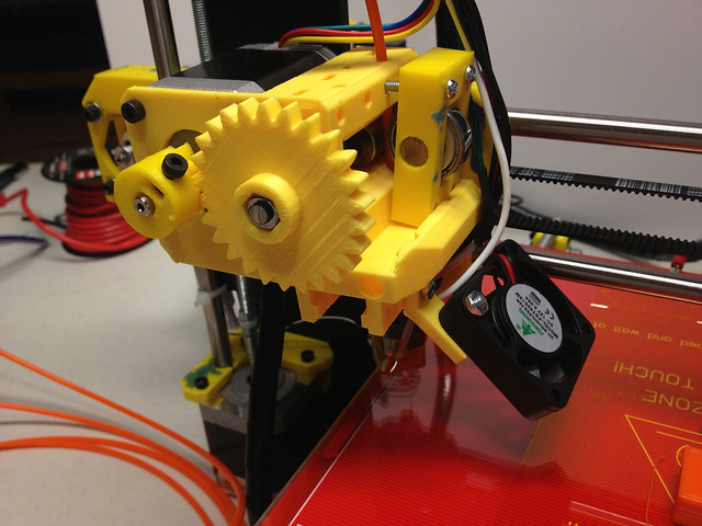
The first step on my "machined" version of sgraber's i3ext ( +Shane Graber ) ... Gearing:


OpenScad Parametric Involute Bevel and Spur Gears (GregFrost on Thingiverse)
A quick summary of where the involute gear comes from:
Spur gears are pretty much what most people think of when you say "gear" (disks with teeth). The involute curve is the result making sure the teeth transmit power evenly, don't collide, or get stuck. Basically square teeth will scrape on the way in, get stuck when they mesh, and scrape on the way out. So "round them off", in a mathematical sense. The involute curve is a curve formed from another curve! The common example used is to tie a pencil to a spool of thread and "unwrap" the spool with the pencil. The result is a curve with an continuously increasing radius (from wikipedia):

The main components of the involute gear
Designing the gears we need.
I'll admit I based most my decisions on how many teeth, what pitch, etc by just looking at what was in the pictures on the RepRap Wiki and Thingiverse.While most books, and articles, go into great detail about every formula to calculate every gear component, Ivan Law was nice enough to mention that it is for completeness only, and you will only use a few of them in practice ( at least for machining a hobby level gears).
Basically all we need is the Outside Diameter(OD), which is size of the disc that we will cut the teeth into, the Pitch Circle Diameter(PCD), which is the theoretical disc that is used to design the actual gear spacing and drive ratios, and D+f, which is how deep we cut.(Depth of tooth + clearance)
Gear Formulas Used:
$$ OD = \frac{N+2}{DP} $$
$$ PCD = \frac{N}{DP} $$
$$ C2C= \frac{PCD_1 + PCD_2}{2} $$
$$ D+_f= \frac{2.157*}{DP} $$
Where:
N = Number of Teeth: The total number of teeth on the gear
DP = Diametral Pitch. This is the number of teeth per inch.(along the Pitch Circle )
*Module (M) Is the length per tooth in mm, and is the reciprocal of DP and converted to metric.
So, instead of teeth per length, module is length per tooth (converted to metric):
OD = Outside Diameter: This is the disc size that the cutter is machined from.
PCD = Pitch Circle Diameter: The theoretical gear size used during design.
C2C = Center-to-Center: The distance from center of one gear to the center of another. This distance will determine the stepper motor and drive gear location.
D+f = The full depth of the tooth plus the tooth clearance. The amount we feed the cutter into the blank.
So looking at the Open Scad files, we see a 26 toothed large gear and a 9 toothed small gear, which is about 3:1 gear reduction from the stepper to the filament drive gear axle.
* In practice you choose the small gears tooth count first, then you design the big gear to meet the desired drive ratio. Ivan suggests not going any smaller than 16 teeth, which doesn't work for these tiny printer parts. This is addressed below in the "making gear cutters" section.
module big_gear() {
 difference() {
  translate ([0,0,0])
   gear(number_of_teeth=26,
     circular_pitch=300,
     rim_thickness=5,
     bore_diameter=6.2
     );
  translate ([0,0,6]) cylinder(r=10.2/2, h=5, $fn=6);
 }
}


module small_gear() {
 translate([29,0,0]) {
  difference(){
   rotate([0,0,360*-1/10])
    gear(number_of_teeth=9,
      circular_pitch=300,
      rim_thickness=15,
      hub_thickness=17,
      hub_diameter=18.5,
      gear_thickness=8,
      bore_diameter=6.4
      );
   translate([-3.25,3.75,9]) cube([6.5,3.2,9]);
   translate([0,0,9+3.5]) rotate([-90,0,0])
    cylinder(r=1.75, h=20, $fn=10);
  }
 }
}
Code snippet from gears.scad
Plugging the number of teeth and pitch into the formulas above we get the following:
| GLOBAL | GEARS | Center-to-Center = 30.16 mm | ||||
|---|---|---|---|---|---|---|
| Diametral Pitch | 16 | Large | Small | |||
| Pressure Angle | 30 | Outside Diameter (OD) | 49.21 mm | 17.46 mm | ||
| Depth of Cut (D+f) | 3.42 mm | Pitch Circle Dia. (PCD) | 46.04 mm | 14.29 mm | ||
| Module | 1.588 mm | |||||
So: Now we know we need a gear blank with a 49.21 mm diameter and a gear blank with a 17.46 mm diameter. We also know that the stepper shaft and drive gear axle need to be 30.16 mm apart.
Update: I drew a 3D version of the i3ext( modified), based on measurements from the scad file, and my gear calculations didn't result in the same center-to-center distance of the axles. Could be a different pressure angle or who knows. I'll have to get on the #reprap irc channel and see :) So, as a result I chose a 29 tooth large gear. It's not that I need match the original exactly, but the bearing housing and stepper motor size limit how much you can change the original design. It was easier to enlarge the gear to match. Now onto actually cutting the gears.
Gear Cutters and Tool costs associated with the curve complexity:
Without going into detail, a different shaped cutter is required for gears of different diameters, pressure angles, and pitch. If you consider every possible permutation, it is a ton of cutters. This makes sense when you compare a tiny radius, 9 tooth, gear (as on the extruder stepper) to a straight rack and pinion style gear (of infinite radius). This is where the "close enough" factor comes into play. They make sets of cutters (no. 1-~10), where each cutter can cut a small range gears with different number of teeth: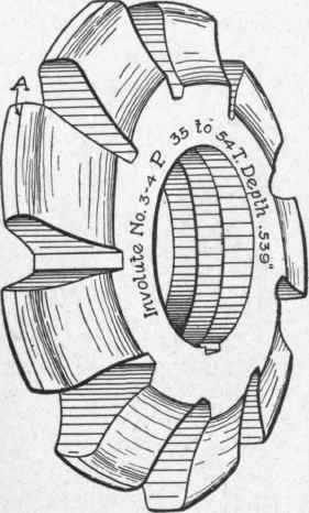
This helps, but you still need a different set for every different pressure angle. The next obvious question from cheapskates, like myself, is "can I make my own gear cutters"? And the answer is yes. You need a tool to make a tool. That is to say, we use a fixed radius cutting tool to cut a fixed radius cutter to approximate the continuously increasing radius profile of an involute gear cutter. :)
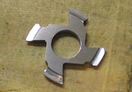
Single Point Cutting Tool:
My understanding is that even the multi-tooth cutter above is a "Single Point" tool because it only cuts one gear tooth at a time (B&S terminology). I initially thought it meant a single cutter edge, like on a fly cutter (which will also work). So, we take a disc (or square) of steel, shape the perimeter similar to an involute gear cutter's profile, cut away some material leaving teeth which can cut a single gear tooth. (technically it removes the material between 2 teeth).This picture is from a great pictorial of the processes::Making Multi-Point Gear Cutters:
The Button Tool: How to create the correct tool profile to shape the gear cutter.
The button tool consists of a mild steel holder with a couple of hardened disc-shaped cutters(buttons) mounted at a fixed center-to-center distance. This way we can cut the "approximate involutes" on both sides of the gear cutter at the same time while keeping the gear cutter symmetric.
This is an over-simplified depiction. In reality we need to account for chip clearance, rake angle, relief angles, etc by offsetting the disc either while shaping the disc, or offsetting the tool during the machining process.
Issues with the button tool method
For every involute( or range) a different button tool is needed. Each button tool has a unique disc size, center-to-center distance, and required infeed. This isn't as bad as seems for the extruder since we only need two gears. Gears and Gear Cutting contains a couple tables containing the required button parameters. However, there are a few problems: First, there is no information for the small 9 tooth gear we need on the stepper. Second, he only shows values for 20 and 30 degrees pressure angles (even though I am using 30). Third, he doesn't show where the data in the tables came from, so we can't calculate our own.I searched web and found the following article on Mike's Workshop : Designing Gear Cutters. He ran into the same problem and using trig/geometry figured out the formulas and relationships. So, using the following relationships, along with the desired pitch(or module), and number of teeth, we can create smaller button tools to make smaller gear cutters.
Again, glossing over much of the information / derivations, it boils down to these three formulas:
$$ bd = NM\cdot sin(p) $$ $$ bs = NM\cdot Cos(p)\cdot sin(p + \frac{90}{N}) $$ $$ inf = \frac{M\{ N\cdot Sin p - (N-2.314) + N \cdot Cos(p)\cdot Cos(p + \frac{90}{N})\}}{2} $$
Where:
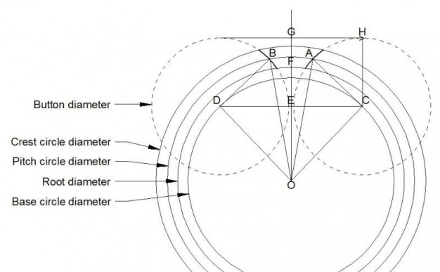
- bd. Button Diameter
- bs. Button Separation (C,D in diagram)
- inf. Infeed (G,F in diagram) The distance from point G to the root circle. So, I can "touch off" the button tool tangent to the buttons and feed to proper depth. *remember this just to create the gear cutter, not the gear.
- Number of teeth (N). This is simply the number of teeth on the gear.
- Pressure angle (p). This is the angle AOC in the diagram above. A line drawn from the intercept of the gear tooth with the pitch circle forms a tangent to the base circle at the pressure angle.
- Module (M). This is the pitch circle diameter divided by the number of teeth. Thus pcd = NM.
- *M = 25.4/DP (module is the reciprocal of DP, but in metric)
Plugging in numbers to the formulas above, and combining them with the gear specs from above, we now have everything we need to make two tools, to make two gear cutters, to make two gears, to make an extruder, to make a printer, to make...
| GLOBAL | GEARS | Center-to-Center = 30.16 mm | ||||
|---|---|---|---|---|---|---|
| Diametral Pitch | 16 | Large | Small | |||
| Pressure Angle | 30 | Outside Diameter (OD) | 49.21 mm | 17.46 mm | ||
| Depth of Cut (D+f) | 3.42 mm | Pitch Circle Dia. (PCD) | 46.04 mm | 14.29 mm | ||
| Module | 1.588 mm | |||||
| BUTTON TOOL | ||||||
| Number of Teeth | 29 | 9 | ||||
| Button Diameter | 23.02 | 7.14 | ||||
| Button Separation | 21.77 | 7.95 | ||||
| Button Tool Infeed | 7.03 | 3.00 | ||||

I created the these gears in 3D using a virtual button tool to create a cutter shaped solid that I subtracted from the gear blank
References:
Wikipedia - Involute Gear
Ivan Law's Gears and Gear Cutting
John Stevenson - Cutting Involute Gears With Form Tools
Mike's Workshop - Designing Gear Cutters
Dean Williams - Making Multi-Point Gear Cutters (pictorial)
Shane Graber's i3ext Extruder - sgraber on Github
Parametric Involute Bevel and Spur Gears by GregFrost - Github
Designing Involute Profile Gear Pairs in Art of Illusion - RepRap Wiki